Search...
What Are You Looking For?
1 Introduction
The concept of refractory high-entropy alloys was proposed by Senkov et al. [1] and gained attention due to their ability to maintain yield strengths exceeding 400 MPa at 1600°C. Compared to conventional high-temperature alloys, refractory high-entropy alloys exhibit superior high-temperature mechanical properties, making them particularly suitable for high-temperature thermal protection and load-bearing components [2-3]. These alloys primarily consist of refractory metallic elements such as Nb, Mo, Ta, W, Hf, and Zr [4-6], with melting points generally exceeding 2000 K. Consequently, refractory high-entropy alloys exhibit outstanding high-temperature resistance and high strength [7-9], enabling them to meet the demands of aerospace applications for high-temperature load-bearing structures and thermal protection systems. Thus, these alloys hold significant potential for critical components operating in extreme high-temperature environments.
The high melting point of refractory high-entropy alloys poses challenges for their fabrication techniques. Current primary preparation methods include arc melting, induction melting, laser melting, and electron beam melting. Senkov et al. [1] utilized vacuum melting technology to prepare NbMoTaW refractory high-entropy alloy, which exhibited high compressive yield strength at elevated temperatures. Han et al. [10] employed arc melting to produce novel TiNbMoTaW and TiVNbMoTaW refractory high-entropy alloys. Compared to NbMoTaW and VNbMoTaW high-entropy alloys (HEAs), both alloys exhibited significantly enhanced room-temperature yield strength and compressive plastic strain. Zou et al. [11] investigated the influence of size effects on the plasticity of arc-melted NbMoTaW refractory high-entropy alloys. They found that compared to pure body-centered cubic (BCC) metals, the size dependence in refractory high-entropy alloys (RHEAs) is reduced due to the presence of greater lattice distortion. However, these methods were all performed in high-purity inert atmospheres or high vacuum. The complexity of compositions and vast differences in melting points among constituents readily lead to pronounced solidification defects, including micro- and macro-segregation in dendritic forms and porosity. Concurrently, the high hardness and brittleness of refractory high-entropy alloys at room temperature render their machining exceptionally challenging. The fabrication of precision complex components from these alloys is particularly difficult, limiting their applications.
Selective Laser Melting (SLM) technology overcomes the shortcomings and limitations of traditional manufacturing processes. As a form of additive manufacturing (3D printing), laser melting relies on the rapid computational capabilities of computer software to slice a three-dimensional part into multiple two-dimensional layers parallel to the processing plane. Each layer is then divided into linear movement trajectories for a laser point source. During forming, a high-energy laser beam heats and melts metal powder. The rapidly moving spot forms molten channels that overlap to create the processing plane. Each processing plane is accumulated layer by layer, ultimately achieving high-precision complex three-dimensional part formation [12-13]. Due to the high flexibility of additive manufacturing technology, methods for preparing refractory high-entropy alloys using this technology and related laser processing techniques have garnered increasing attention. Zhang et al. [17] employed laser cladding to fabricate a novel refractory high-entropy alloy coating of TiZrNbWMo, exhibiting high thermal stability with hardness exceeding three times that of the substrate. Li et al. [18] prepared WxNbMoTa refractory high-entropy alloys (x% denotes atomic fraction) via laser cladding. They observed that W content had negligible effect on phase structure but hardness exhibited an increasing trend with rising W content. Dobbelstein et al. [19] employed laser deposition manufacturing to fabricate MoNbTaW refractory high-entropy alloys, investigating the influence of powder state on the deposition process. Zhang et al. [20] fabricated NbMoTaW refractory high-entropy alloys using SLM technology, observing that SLM samples exhibited significantly smaller grain sizes than cast samples, along with exceptionally high hardness (826 HV) and corrosion resistance (self-corrosion current Icorr = 8.716 × 10⁻¹¹ A). Zhang et al. [21] employed SLM to fabricate a novel NbMoTaTi₀.₅Ni₀.₅ refractory high-entropy alloy. They observed that adding Ni and Ti elements suppressed the crack sensitivity of NbMoTa alloys, significantly improving the formability of the refractory high-entropy alloy while maintaining its high-temperature properties. Zhang et al. [22] investigated the thermodynamic behavior of WTaMoNb refractory high-entropy alloys fabricated via selective laser melting (SLM) through experimental and simulation methods. By establishing a thermal behavior model for the SLM process, they simulated temperature distribution, thermal stress, and strain during SLM. Simulation-based optimization of SLM process parameters reduced thermal stress and strain. However, the high cooling rates and wide cooling temperature range during processing result in significant residual stresses in MoNbTaW refractory high-entropy alloys produced via additive manufacturing. All such alloys exhibit noticeable defects [17-25].
To address the high brittleness of MoNbTaW refractory high-entropy alloys at room temperature, this study combined SLM technology with alloying methods to prepare two refractory high-entropy alloys: (NbMoTaW)100-xCx (x% = 0, 0.5%) and NbMoTaWTix (x% = 0.125, 0.250, 0.500) refractory high-entropy alloys. This approach simultaneously enhances the strength and ductility of MoNbTaW alloys, with detailed analysis of their microstructures and mechanical properties. These findings provide novel insights and theoretical foundations for overcoming defect suppression and stress regulation challenges in additive manufacturing of refractory high-entropy alloys, paving the way for fabricating large-scale heat-shielding structural components.
2 Experimental Materials and Methods
2.1 Experimental Equipment and Materials
The experimental setup employed a 3D printer equipped with an Nd:YAG fiber laser, operating at a maximum power of 500 W. The powders used were Nb, Mo, Ta, W, and Ti powders, along with pre-alloyed WC powder with a particle size of ~500 nm, all with a mass fraction of 99.9%. The powders primarily exhibited spherical particles, as shown in Figure 1(a), with particle sizes ranging from 15 to 53 μm, as illustrated in Figure 1(b). Mechanical mixing was performed using a planetary ball mill for 12 hours. Subsequently, the powders were placed in a vacuum chamber at 120°C for 4 hours to remove moisture and enhance powder flowability.

2.2 Experimental Method
During the SLM forming process, high-purity argon gas is introduced into the forming chamber to ensure that the oxygen content (volume fraction) within the chamber remains below 4×10⁻⁴ during printing, thereby protecting the sample from oxidation. Tungsten plates, manufactured via powder metallurgy with a thickness of 8 mm and a surface area of 30 mm × 30 mm, are utilized as the substrate. To minimize residual stresses generated during processing, the tungsten substrate is preheated to 180°C [26]. Figure 2(a) shows a simplified schematic of the SLM processing. Optimal SLM process parameters were determined through multiple orthogonal experiments to produce specimens with well-formed surfaces and free from defects such as macroscopic cracks. During scanning, the scan path rotated by 67° after each layer was formed, as shown in Figure 2(b). Here, XYZ represents the spatial coordinate system, where XY denotes the substrate plane, Z indicates the printing direction, and N represents the number of printed layers. This process was repeated until the specimen was fully formed. Ultimately, an 8 mm × 8 mm × 5 mm bulk specimen and a cylindrical compression specimen with a diameter of 2 mm and height of 4 mm were directly fabricated using SLM.
2.3 Material Characterization Methods
The relative density of the specimens was determined through industrial computed tomography (CT) analysis. The phase composition of the specimens was analyzed using an X-ray diffractometer (XRD) within the 10°–100° range. Electron backscatter diffraction (EBSD) analysis was performed on the specimens using a scanning electron microscope (SEM) to determine their phase distribution. Prior to EBSD characterization, the alloy surface was ground using SiC abrasive paper of varying grit sizes, followed by fine grinding with 0.05 mm Al₂O₃ particles and vibratory polishing. Samples were then rinsed with ethanol and air-dried. Microstructural observation was performed using a transmission electron microscope (TEM). The compressive properties of the alloy specimens were measured using a computer-controlled universal testing machine at a strain rate of 10⁻³ s⁻¹. Specimen dimensions were φ2 mm × 4 mm (φ denotes diameter), with compressive strain calibrated using an extensometer. At least five specimens were tested for compressive properties, and the average value of the test results was calculated to ensure accuracy. Finally, SEM was used to observe the fracture morphology of the specimens.

3 Analysis and Discussion
3.1 Microstructure and Property Analysis of (NbMoTaW)100-xCxRHEA
3.1.1 Microstructural Analysis
Macroscopic morphology of (NbMoTaW)100-xCxRHEA (x% = 0, 0.5%) was photographed on a plane perpendicular to the printing direction. Relative density was determined using 3D-CT, as shown in Figure 3. Macroscopic morphology and 3D-CT results revealed no cracks in the specimens, only a small number of pores with dimensions less than 23 µm, as shown in Figure 3(b). The 3D-CT results indicated a density of 99.6% for (NbMoTaW)99.5C0.5RHEA, demonstrating its excellent formability.

The XRD patterns of (NbMoTaW)100-xCxRHEA are shown in Figure 4. It can be observed that the NbMoTaW alloy exhibits a single-phase BCC structure with a lattice constant of 3.216 Å. The (NbMoTaW)99.5C0.5 alloy additionally contains an NbC phase with a lattice constant of 4.428 Å.
The EBSD results for (NbMoTaW)100-xCxRHEA are shown in Figures 5 and 6. The microstructure of (NbMoTaW)100-xCxRHEA consists of numerous elongated grains and a small number of equiaxed grains, as depicted in Figures 5(a) and 5(b). Nb, Mo, Ta, and W elements are nearly uniformly distributed in (NbMoTaW)99.5C0.5 and NbMoTaW RHEA, though minor C atom clustering occurs in (NbMoTaW)99.5C0.5. Statistical analysis results for grain boundary distribution, grain size, and local orientation deviation in (NbMoTaW)100-xCxRHEA are presented in Figure 6. Generally, interfaces with angles between 2° and 15° are considered subgrains, while those exceeding 15° are classified as grain boundaries. As shown in Figures 6(a) and (b), (NbMoTaW)99.5C0.5RHEA exhibits a high proportion of subgrains (approximately 73.6% area fraction) with an average grain size of 10.6 μm; In contrast, the (NbMoTaW)99.5C0.5RHEA sample exhibits a subgrain boundary content of 54.8% (area fraction) with an average grain size of 18.4 μm, indicating that C microalloying effectively increases the subgrain boundary content and refines the grain size. Additionally, (NbMoTaW)99.5C0.5RHEA exhibits a higher geometric necessity dislocation (GND) density, as shown in Figures 5(c) and (d). Detailed statistical results for the kernel (local) average misorientation (KAM) are presented in Figure 6(c). The average KAM value for (NbMoTaW)99.5C0.5RHEA is 2.3°, with a smaller area fraction in the 0°–1° range, approximately 4.6%. The KAM average for NbMoTaW RHEA is 1.4°, with an area fraction in the 0°–1° range of approximately 29.2%, indicating that C microalloying effectively increases the GND density.


3.1.2 Precipitate Phase Analysis
Figure 7 shows TEM images of (NbMoTaW)100-xCxRHEA. Figures 7(a) and (b) reveal numerous finely dispersed precipitates in (NbMoTaW)99.5C0.5RHEA, primarily distributed at grain boundaries and dislocations, with a small amount present within grains as shown in Figure 7(d). The selected area electron diffraction (SAED) pattern of (NbMoTaW)99.5C0.5RHEA exhibits an additional diffraction spot distinct from NbMoTaW [Figure 7(b)]. On the [111] body-centered cubic (BCC) crystal zone axis [27], the [110] plane of the precipitation phase is parallel to the [1-10] plane of the matrix BCC phase. Analysis of the precipitate phase using high-resolution TEM (HRTEM) and EDS revealed it consists of polygonal particles with a diameter of 58 nm. EDS results indicate the precipitate is predominantly enriched in Nb and C elements, as shown in Figure 7(c). At grain boundaries, the precipitate exhibits a strip-like distribution with lengths of 90–110 nm and widths of 40–60 nm [Figure 7(d)]. To determine the precise composition of the precipitates, their atomic structure was further characterized using HRTEM images along the [001] BCC crystal zone axis, as shown in Figure 7(e). Fourier transform (FFT) analysis of both the matrix region and the precipitates confirmed the presence of the NbC phase, consistent with the XRD results. The interplanar spacings of the [1-10]BCC and [020]NbC planes were approximately 0.222 nm and 0.213 nm, respectively. On the [100]BCC crystal zone axis, a [010]NbC∥[1-10]BCC phase relationship existed between the matrix and the NbC precipitation phase. The interplanar spacings between [110]BCC and [1-10]NbC are approximately 0.222 nm and 0.308 nm, respectively. A [200]NbC∥[110]BCC phase relationship exists between the matrix and the NbC precipitation phase, as shown in Figure 7(f). Calculations yield lattice parameters for the precipitate of ~0.417 nm, closely matching the theoretical NbC lattice parameter of 0.419 nm. The precipitation of NbC not only enhances alloy strength through dispersion strengthening but also promotes grain refinement in (NbMoTaW)100-xCxRHEA by pinning dislocations and grain boundaries.
3.1.3 Compression Performance Analysis
The compression stress-strain curve of (NbMoTaW)100-xCxRHEA is shown in Figure 8(a). Microalloying with 0.5% carbon significantly enhances the strength and ductility of SLMed NbMoTaW. The compressive yield strength and fracture strength of NbMoTaW RHEA increased markedly from 1183 MPa and 1214 MPa to 1695 MPa and 1751 MPa, representing improvements of 43.3% and 44.2%, respectively. while ductility increased substantially from 3.9% to 6.9%. To elucidate the fracture mechanism, fracture surfaces of (NbMoTaW)100-xCxRHEA were examined, as shown in Figures 8(b) and (c). Results indicate that the fracture surface of NbMoTaW RHEA exhibits a relatively smooth morphology with cleavage-like features, characteristic of brittle fracture. The fracture surface of (NbMoTaW)99.5C0.5RHEA exhibited sharp tearing edges and intergranular microcracks. This indicates that adding carbon with an atomic fraction of 0.5 transformed the fracture mechanism of NbMoTaW RHEA from a brittle mode to a brittle-ductile hybrid mode. The strength and ductility of NbMoTaW RHEA are significantly enhanced by the microalloying effect of 0.5% carbon by atomic fraction.
As mentioned earlier, carbon microalloying refines the grain structure of (NbMoTaW)99.5C0.5RHEA and promotes the precipitation of numerous nanoscale NbC particles. During SLM processing, rapid cooling rates readily induce thermal residual stresses, resulting in high dislocation density within NbMoTaW RHEA. In contrast, within (NbMoTaW)99.5C0.5RHEA, C exists as an interstitial solid solution within the matrix, partially inhibiting dislocation motion induced by thermal deformation. The SLM-fabricated (NbMoTaW)99.5C0.5RHEA exhibits higher dislocation density. Under thermal cycling, substantial NbC particles precipitate at grain boundaries and dislocations (Figure 7), producing pronounced pinning effects that suppress grain coarsening in NbMoTaW RHEA during thermal cycling. The microstructural changes induced by C microalloying in NbMoTaW RHEA enhance its mechanical properties. The abundant NbC particles exhibit a pronounced precipitation strengthening effect, significantly improving the strength of (NbMoTaW)99.5C0.5RHEA. Additionally, the plasticity of NbMoTaW RHEA is markedly enhanced after C microalloying. This occurs because C atom microalloying suppresses O segregation at grain boundaries, ensuring stronger matrix bonding and inhibiting intergranular cracking [28]. Overall, C microalloying simultaneously enhances both strength and ductility in SLM-fabricated (NbMoTaW)99.5C0.5RHEA, achieving a favorable balance.
3.2 Microstructure and Property Analysis of NbMoTaWTix RHEAs
3.2.1 Microstructural Analysis
NbMoTaWTix RHEAs (x% = 0.125, 0.250, 0.500, denoted as NbMoTaWTi0.125, NbMoTaWTi0.250, and NbMoTaWTi0.500, respectively). The standard chemical compositions of NbMoTaWTix RHEAs are shown in Table 1. The XRD patterns of printed NbMoTaWTix RHEAs are depicted in Figure 9. Only a single-phase BCC structure was observed in the XRD patterns of all printed NbMoTaWTix RHEAs. As the Ti content increased, the diffraction peaks of the samples gradually shifted to the left. Consequently, the lattice constant of NbMoTaWTix RHEAs increased from 3.216 Å in NbMoTaW RHEA to 3.224 Å in the NbMoTaWTi0.5 alloy. Among the elements present in NbMoTaW, Ti possesses the largest atomic radius. Therefore, as Ti content increases, its dissolution leads to an increase in the lattice constant of NbMoTaWTix RHEAs.


The backscattered electron (BSE) image of NbMoTaWTix RHEAs is shown in Figure 10. It can be observed that the grains in NbMoTaWTix RHEAs are relatively fine, with numerous dislocation cells and other sub-structures present within the grains. Changes in Ti content have little effect on the microstructure morphology of NbMoTaWTix RHEAs. No cracks were detected in any of the three alloys; however, similar to (NbMoTaW)100-xCxRHEA, a small number of fine pores (less than 10 µm) were present.
EBSD results for NbMoTaWTix RHEAs are shown in Figure 11. The microstructure consists of partially elongated grains and a small number of fine grains. With increasing Ti content, the proportion of high-intensity regions in the {100} pole figure of NbMoTaWTix RHEAs progressively increases, indicating a more pronounced [100] preferred orientation. Nb, Mo, Ta, W, and Ti elements exhibit nearly uniform distribution throughout the NbMoTaWTix RHEAs, indicating no macroscopic segregation. Ti atoms uniformly solid-solve into the NbMoTaW matrix, forming a single-phase BCC structure. With increasing Ti content, the grain size of NbMoTaWTix RHEAs shows little change, and grain size variation has no significant effect on mechanical properties. Instead, the solid solution strengthening effect of Ti plays a primary role in enhancing strength.


3.2.2 Compressive Performance Analysis of NbMoTaWTix RHEAs
The compression stress-strain curves of NbMoTaWTix RHEAs are shown in Figure 12(a), with corresponding mechanical parameters listed in Table 2. Here, σ₀.₂ denotes yield strength, σ_p denotes compressive strength, and ε_p denotes strain. With increasing Ti content, the yield strength, compressive strength, and strain of NbMoTaWTix RHEAs all significantly improve. Compared to NbMoTaW, NbMoTaWTi0.5RHEA exhibits yield strength, compressive strength, and strain increases of 20.7%, 30.7%, and 117.9%, respectively. The variation of yield strength and compression ratio with Ti content is depicted in Figure 12(b). The yield strength of NbMoTaWTix RHEAs increases rapidly with the addition of a small amount of Ti, and the rate of increase gradually decreases as the Ti content increases. Meanwhile, the compressive strain of NbMoTaWTix RHEAs increases approximately linearly with increasing Ti content.
As previously noted, Ti has a larger atomic radius than Nb, Mo, Ta, and W. Consequently, increasing Ti content gradually enlarges the lattice constant of NbMoTaWTixRHEAs after Ti solid solution. Furthermore, studies [10, 29-30] indicate that Ti addition enhances the intergranular cohesive strength of NbMoTaWTix RHEAs, effectively suppressing intergranular crack propagation and thereby improving plasticity. Consequently, both strength and plasticity of SLM-fabricated NbMoTaWTix RHEAs increase with rising Ti content.

4 Conclusions
To address the brittleness issue of NbMoTaW refractory high-entropy alloys at room temperature, two types of refractory high-entropy alloys—(NbMoTaW)100-xCx (x% = 0, 0.5%) and NbMoTaWTix (x% = 0.125, 0.250, 0.500)—were prepared by combining SLM technology with alloying methods. The following conclusions were drawn:
1) By integrating laser selective melting technology with alloying methods, two RHEAs—(NbMoTaW)100-xCx and NbMoTaWTix—were fabricated. Alloying with C and Ti enhanced the room-temperature brittleness resistance of the NbMoTaW RHEA.
2) A well-formed (NbMoTaW)99.5C0.5 RHEA with 99.6% density was fabricated using laser selective melting. Results indicate that the addition of 0.5 atomic % C refined the grain structure of the NbMoTaW RHEA and precipitated NbC nanoparticles. The microalloying effect of 0.5 atomic % C increased the yield strength and fracture strength of the NbMoTaW RHEA by 43.3% and 44.2%, respectively, while the plasticity improved from 3.9% to 6.9%.
3) Well-formed NbMoTaWTix RHEAs were fabricated using laser selective melting technology. Results indicate that all NbMoTaWTix RHEAs exhibit a single-phase BCC structure, with lattice constants gradually increasing as Ti content rises. The addition of Ti effectively enhances the strength and ductility of NbMoTaW RHEAs. With increasing Ti content, the yield strength, compressive strength, and ductility of NbMoTaWTix RHEAs all significantly improved by 20.7%, 30.7%, and 117.9%, respectively.
4) Laser selective melting technology enables the fabrication of complex components with a single dimension of 100 mm, facilitating the further application of NbMoTaW RHEAs.
References:
Study on Microstructural Toughening and Properties of Laser Selective Melting NbMoTaW Refractory High-Entropy Alloys (Invited)
Chinese Library Classification: V252 Document Type: A DOI: 10.3788/CJL231581
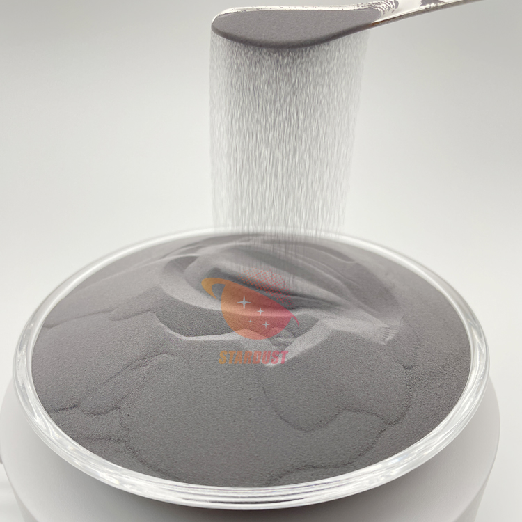
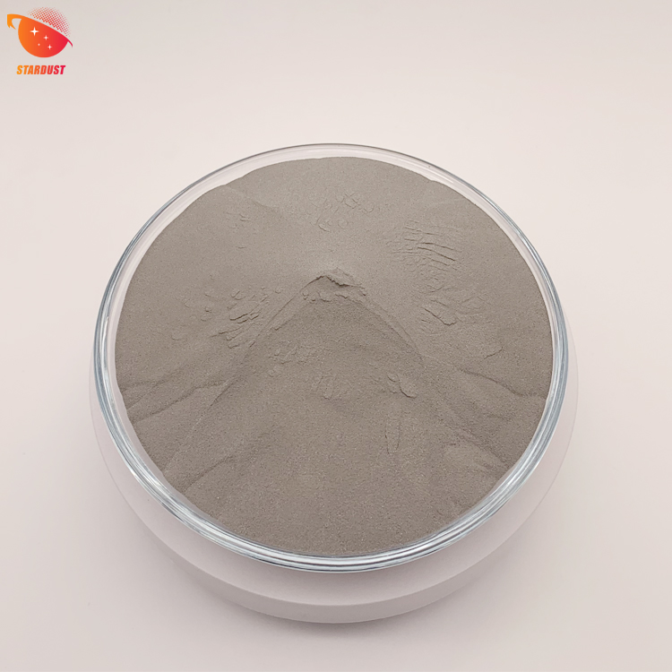
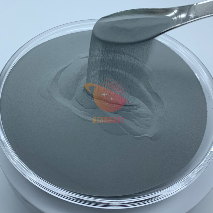
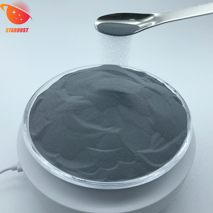
Stardust Technology's radiofrequency plasma spheroidization technology produces tungsten-molybdenum-tantalum-niobium (W-Mo-Ta-Nb) and tungsten-molybdenum-tantalum-niobium-vanadium (W-Mo-Ta-Nb-V) alloy powders characterized by high purity (≥99.9%), low oxygen content, high sphericity, smooth surface, absence of satellite particles, uniform particle size distribution, excellent flowability, and high tap density. Their performance advantages include outstanding high-temperature stability, high strength, high hardness, exceptional wear resistance, and corrosion resistance. These powders are primarily used in high-end applications such as defense, aerospace, and nuclear industries for processes including laser/electron beam additive manufacturing (3D printing), hot isostatic pressing, metal injection molding, and laser cladding. Stardust Technology offers customized particle size options and corresponding packaging services based on customer requirements. For details, please contact our professional manager: Cathie Zheng at +86 13318326187.


Signup our newsletter to get update information, promotion and insight.


 IPv6 network supported