1 Introduction
Ti65 titanium alloy is a near-α high-temperature titanium alloy developed based on Ti60 titanium alloy [1]. It possesses excellent high-temperature strength, creep resistance, and corrosion resistance, maintaining stable performance under long-term service conditions at approximately 650°C. It is widely used in high-temperature components such as aircraft engine blades [2]. Nb521 niobium alloy is currently the most widely used high-temperature niobium alloy. It features a high melting point (approximately 2480°C), good plasticity, and excellent high-temperature structural stability. Additionally, it offers favorable machinability and formability, making it commonly used in the manufacture of critical components for aerospace engines, weapon propulsion systems, dual-component liquid engines for rockets and missiles, and nuclear reactors [3-5]. Ti65 titanium alloy possesses high specific strength and significant lightweight advantages, while Nb521 niobium alloy exhibits outstanding high-temperature performance. Their synergistic application in hypersonic vehicle thermal protection structures holds great engineering value, promising to meet structural weight reduction requirements while ensuring reliable service under extreme high-temperature conditions.
Brazing, characterized by low heating temperatures, minimal residual stresses, and suitability for joining dissimilar materials, is widely employed for connecting high-temperature titanium alloys with refractory metals. Extensive research has explored brazing of Nb-based alloys. SU et al. [6] achieved reliable Nb521/GH99 bonding using Ti-35Ni brazing filler metal. Phase evolution of Ti₂Ni and TiNi₃ in the joint significantly influenced mechanical properties, yielding a maximum shear strength of 121 MPa at 1120°C/10 min. Sun Yan et al. [7] employed a Ti-Zr-Cu-Ni/Ti composite filler metal to join Cf/SiC/Nb. The TiC and β-(Ti, Nb) phases formed at the interface were jointly controlled by carbon diffusion and Nb dissolution. TIAN et al. [8] brazed C/SiC/Nb using Ti-Ni foil, maintaining a shear strength of 82 MPa at 1000°C, validating the applicability of the Ti-Ni system for Nb alloy joining. The Ti-Ni system readily forms low-melting-point eutectic products with Nb and Ti, effectively promoting wetting and interfacial reactions. Previous studies have demonstrated that Ni foil used for contact reaction brazing of TC4 alloy yields stable interfacial microstructure and high joint strength [9,10], further indicating the potential advantage of Ni foil as a pure metal filler material in the Ti/Nb system.
Based on this, this study employed contact reaction brazing of Ti65/Nb521 using Ni foils of varying thicknesses under conditions of 1150°C/20 min/0.1 MPa. By characterizing interfacial phase evolution, fracture features, and mechanical properties, the influence of Ni foil thickness on the interfacial formation mechanism was elucidated.
2 Test Materials and Equipment
Ti65 titanium alloy and Nb521 niobium alloy were selected as parent materials, with microstructures shown in Figure 1. Ni foils with thicknesses of 10 μm, 50 μm, and 100 μm were used as interlayers. Ti65 titanium alloy specimens were machined into 10 mm × 10 mm × 5 mm blocks, while Nb521 niobium alloy specimens were machined into 5 mm × 5 mm × 5 mm blocks. All specimen surfaces were sequentially polished using SiC sandpaper ranging from 240-grit to 1000-grit, followed by ultrasonic cleaning in anhydrous ethanol for 15 min and subsequent drying for later use.

Figure 2 shows the assembly schematic of the Ti65/Ni/Nb521 joint. After assembly, the specimen was placed in a vacuum brazing furnace (Model ZTF2-10). During brazing, the vacuum level maintained better than 6×10⁻³ Pa. To ensure uniform heating of the specimen within the furnace, the temperature was first raised at a rate of 10°C/min to 400°C for 10 minutes. Subsequently, the temperature was increased at the same rate to 800°C for 10 minutes. Finally, the specimen was heated at the same rate to the brazing temperature of 1150°C for 20 minutes. After holding at this temperature, the specimen was cooled at a rate of 5°C/min to 500°C, followed by furnace cooling to room temperature.
To ensure the reliability of shear strength data, three specimens were tested for each set of parameters. Shear strength testing was conducted on a universal tensile testing machine (Instron-5982) at a loading rate of 0.5 mm/min. Samples were cut perpendicular to the weld using an electric discharge cutting machine. The post-weld specimens were sequentially ground, polished, and cleaned before microstructural characterization. A JSM-IT800 high-resolution field emission scanning electron microscope (SEM) was employed to examine the microstructure and fracture morphology of the joint, supplemented by energy dispersive spectroscopy (EDS) for compositional analysis. X-ray diffraction (XRD, SmartLab 9kW) was employed to analyze the joint interface and determine its phase composition. Test conditions were: 2θ range 20°–90°, step size 0.01, scan speed 2°/min.

3 Experimental Results and Analysis
3.1 Microstructure and Reaction Mechanism of Ti65/Ni/Nb521 Joint
To investigate the influence of Ni foil thickness on the microstructure of the Ti65/Nb521 brazed joint interface, contact reaction brazing was performed using Ni foils of 10 μm, 50 μm, and 100 μm thicknesses between Ti65 titanium alloy and Nb521 niobium alloy. The microstructure of the interface obtained under the process conditions of 1150°C × 20 min is shown in Figure 3, with the corresponding EDS analysis results presented in Table 1. Ti65/Nb521 joints formed under different Ni foil thicknesses exhibited continuous, dense metallurgical bonding interfaces free of macroscopic defects, displaying a consistent macrostructure of layered phases. The interface can be divided into two main regions: the Ti65-adjacent zone and the Nb521-adjacent zone. The Ti65-adjacent region consists of a gray matrix and acicular Widmanstätten particles. Position A exhibits elevated Nb and Ni content in its elemental composition. Since Ni and Nb are typical β-Ti phase stabilizing elements that significantly lower the transformation temperature from α-Ti to β-Ti, thereby promoting β-Ti phase formation and stabilization, the Nb- and Ni-rich characteristics at Position A indicate its identification as a β-Ti phase [11]. Position B exhibits an elemental composition of 78.62% Ti + 11.51% Al, where Al is an α-phase stabilizing element [12]. Therefore, this region is identified as the α-Ti phase. The region near the Nb521 side primarily consists of a gray solid solution, with EDS analysis showing a composition dominated by Ti and Nb, indicating a (Ti, Nb) solid solution. As the distance toward the Nb521 side increases, the Nb content in the solid solution gradually rises, suggesting that Nb diffuses from Nb521 toward the Ti65 side, forming a gradient distribution. In summary, the Ti65/Nb521 joint interface primarily consists of an α-Ti phase + β-Ti phase structure on the Ti65 side and a (Ti, Nb) solid solution on the Nb521 side, exhibiting a continuous gradient transition structure: Ti65/α-Ti phase + β-Ti phase/(Ti, Nb) ss/Nb521.


According to the binary phase diagrams of Ti-Ni [13] and Ni-Nb [14], the eutectic temperature of Ti-Ni is 942°C, while that of Ni-Nb is 1184°C. The brazing temperature of 1150°C in this study exceeds the Ti-Ni eutectic point but falls below the Ni-Nb eutectic point. Consequently, the initial brazing stage primarily involves a Ti-Ni eutectic reaction between the Ni foil and the Ti65 titanium alloy, forming a Ti-Ni liquid phase. As the Ni foil thickness increases, both Ni and Ti participating in the reaction increase accordingly, leading to a higher volume fraction of the generated Ti-Ni liquid phase. After sufficient reaction with Ti65, the Ti-Ni liquid phase begins to expand toward the Nb521 side, wetting its surface and undergoing further reaction with Nb521. Therefore, at greater Ni thicknesses, the interfacial liquid phase volume is higher and the expansion range is larger, ultimately resulting in a wider weld zone.
When the Ni thickness is 10 μm, the amount of Ti-Ni liquid phase formed is relatively small, resulting in a thin interfacial reaction layer. A large number of fine needle-like α phases can be observed near the Ti65 side. When the Ni thickness increases to 50 μm, the Ti-Ni liquid phase significantly increases, the width of the interfacial reaction zone markedly expands, and the (Ti, Nb) solid solution region further widens. Simultaneously, the needle-like α phase near the Ti65 side gradually transforms from fine and dense to coarse and large. This may be attributed to the increased liquid phase reducing the local cooling rate at the interface, thereby providing more favorable conditions for the growth of the α-Ti phase during cooling. When the Ni foil thickness reached 100 μm, the Ti-Ni liquid phase volume increased further, and the interface layer width reached its maximum. Due to diffusion limitations caused by the excessively high liquid phase volume fraction, Ni element enrichment occurred in some areas. This shifted the local composition into the formation region of the Ti₂Ni phase in the Ti-Ni phase diagram, resulting in the observation of relatively coarse Ti₂Ni phases near the Ti65 side. Figure 3d shows the XRD microarea test results at the 100μm joint, which, combined with EDS results, confirms the presence of Ti2Ni phase at the joint interface.
Figure 4 presents the EDS patterns of the joint interfaces for different Ni foil thicknesses, visually illustrating the distribution of alloying elements within the joint. As shown in Figure 4, Ni and Nb exhibit nearly identical distribution patterns at the joint interface, while Al shows a distribution pattern largely opposite to that of Ni and Nb. These elemental distributions correlate with phase distributions: Ni and Nb, as stabilizing elements for the β-Ti phase, enrich primarily in the β-Ti phase, whereas Al, a stabilizing element for the α-Ti phase, enriches predominantly in the α-Ti phase. During brazing, as alloying elements interdiffuse, the liquid filler metal undergoes a series of phase transformations: L phase → β phase → α phase. According to the Ti-Ni binary phase diagram [13], the solubility of Ni in the β phase is significantly higher than in the α phase. Consequently, during α phase precipitation, excess Ni is repelled toward the phase boundary. For the 100μm Ni foil joint, the higher initial Ni content facilitates localized Ni enrichment in the repelled regions, promoting the formation of Ni-rich intermetallic compounds. Consequently, coarse Ti₂Ni phase precipitates are observable near the Ti65 side. Simultaneously, Al enrichment promotes α-Ti phase precipitation. Near the Nb521 side, higher Nb and Ni concentrations act as β-phase stabilizers, inhibiting α-phase formation. Consequently, this region consists solely of the β-Ti phase.
3.2 Mechanical Properties of Ti65/Ni/Nb521 Joints
Figure 5 shows shear test results for Ti65/Nb521 contact reaction brazed joints under different Ni foil thicknesses. As shown in Figure 5, the shear strengths of the joints were 389 MPa and 394 MPa for Ni foil thicknesses of 10 μm and 50 μm, respectively, significantly higher than the shear strength (198 MPa) observed for the joint with a Ni foil thickness of 100 μm.
To investigate the fracture location and mechanism of the welded joint, the microstructure morphology of the fracture surface was observed. The microstructure morphology under scanning electron microscopy is shown in Figure 6, with corresponding EDS analysis results listed in Table 2. When the Ni foil thickness was 10 μm, the fracture mode exhibited typical intergranular fracture (see Figure 6a). Crack propagation primarily occurred along grain boundaries, closely associated with the formation of a certain amount of brittle Ti₂Ni intermetallic compounds in the interface region. The Ti₂Ni phase tended to continuously precipitate or segregate near grain boundaries, reducing the local grain boundary bonding strength. Under applied shear loading, the brittle Ti₂Ni phase becomes the preferred cracking zone, enabling crack propagation along grain boundaries and exhibiting characteristics of brittle intergranular fracture. When the Ni foil thickness increased to 50 μm, the joint displayed typical ductile fracture behavior (see Figure 6b). The fracture location occurred on the Nb521 parent metal side, indicating that the formed interface possesses high bonding strength. SEM examination of the fracture surface revealed numerous deep, uniformly distributed ductile pits, indicating significant plastic deformation and fracture initiation through a “nucleation-growth-coalescence” mechanism via micro-voids. This confirms that at 50μm Ni thickness, the interface did not exhibit noticeable embrittlement. Instead, its bonding strength exceeded that of the base material, redirecting fracture into the base material and yielding excellent toughness characteristics. When the Ni foil thickness increased to 100μm, cracks in the joint preferentially propagated along the Ti2Ni phase regions (see Figure 7). The joint fracture surface exhibited typical cleavage fracture characteristics (see Figure 6c), with extensive cleavage steps and cleavage planes visible on the fracture surface, indicating brittle fracture of the material. Microstructural analysis of the interface reveals that this fracture mode primarily originates from the extensive formation of brittle Ti2Ni phases at the interface. Their continuous distribution significantly reduces the joint's crack resistance, enabling rapid crack propagation along the Ti2Ni phase zones and ultimately leading to overall cleavage fracture. Therefore, Ni foils with thicknesses of 10 μm and 50 μm facilitate the formation of a continuous, dense, and non-embrittled transition interface structure, thereby maintaining high joint strength. In contrast, the excessive thickness of the 100 μm Ni foil leads to substantial formation of the brittle Ti2Ni phase, making the interface prone to brittle fracture and constituting the primary cause of the significant decrease in shear strength.


4 Conclusion
Contact reaction brazing of Ti65/Nb521 alloy was performed at 1150°C for 20 min using Ni foils of varying thicknesses (10 μm, 50 μm, and 100 μm). Through systematic analysis of interfacial microstructural evolution and mechanical properties, the effects of Ni foil thickness on joint microstructure and performance were investigated. Key conclusions are as follows:
1) All Ti65/Nb521 joints brazed with different Ni foil thicknesses formed dense metallurgical bonds exhibiting a gradient transition structure: Ti65/α-Ti phase + β-Ti phase/(Ti,Nb)ss/Nb521. Thicker Ni foil generated more liquid phase, significantly widening the interfacial reaction layer.
2) The microstructural evolution at the interface changes with increasing Ni foil thickness. The 10μm Ni foil interface formed fine acicular α phase, while the 50μm Ni foil promoted expansion of the reaction zone and coarsening of the acicular α phase. The 100μm Ni foil interface, however, exhibited excessive Ti-Ni liquid phase, leading to extensive formation of the brittle Ti₂Ni phase that distributed continuously across the interface.
Table 2
3) The mechanical properties of the joints are closely related to the interfacial microstructure. The shear strengths of the 10μm and 50μm Ni foil joints were 389 MPa and 394 MPa, respectively. where the fracture location of the 50μm Ni foil joint shifted to the Nb521 base metal side, exhibiting typical ductile fracture characteristics and the best overall mechanical properties. In contrast, the 100μm Ni foil joint experienced cleavage fracture due to the extensive formation of continuous Ti2Ni brittle phases at the interface, resulting in a reduced shear strength of 189 MPa.
Reference: Effect of Ni Foil Thickness on Microstructure and Properties of Ti65/Nb521 Contact Reaction Brazed Joints; Zhu Han, Bi Jianxun, Li Dong, Li Hongli, Zhao Chenhao, Liang Debin, Li Botao, Kang Li;
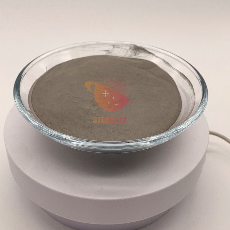
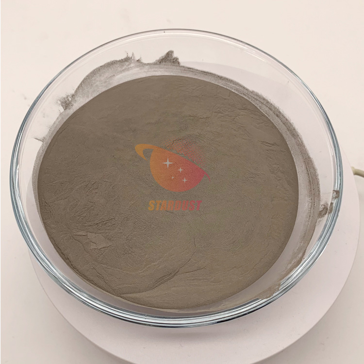
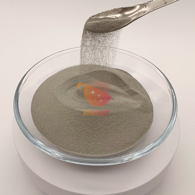
Stardust Technology's spherical Nb521 alloy powder achieves a stable microstructure through the synergistic effects of solution strengthening and precipitation hardening. This technical approach not only optimizes strength-toughness matching at room temperature, ensuring high strength and deformation resistance after component forming, but more importantly, maintains exceptional dimensional stability and creep resistance under high-temperature conditions. It provides reliable material assurance across the entire spectrum from room temperature to high temperatures for critical components in aerospace, nuclear energy, and other fields. For more product information, please contact Manager Cathie Zheng at +86 13318326187.


 IPv6 network supported