Search...
What Are You Looking For?
0 Preface
Titanium-zirconium-molybdenum (TZM) alloys, also known as TZM (Ti-Zr-Mo) alloys, are characterized by high melting points, high strengths, low coefficients of thermal expansion, and excellent high-temperature mechanical properties, which have been widely used in the military industry, aerospace, and other fields, such as rocket nozzles, fuel lines, and nozzle pipe throat linings [1]. Tungsten rhenium (WRe) alloy has a high melting point, high strength, high plasticity, high recrystallization temperature and low toughness and brittle transition temperature [2]. Especially important is that tungsten rhenium alloy has excellent high temperature mechanical properties, can be used in 2000 ℃ under the conditions of ultra-high temperature structural materials, typical applications include solid rocket engine nozzle [3], fusion reactor in the first wall of the material [4] and the extreme environment of the thermocouples [5] and so on. Effective joining of TZM alloys with WRe alloys is the key to expanding the applications of refractory alloys in aerospace and other fields.
However, the large differences in the physical and chemical properties of these two materials make the connection between them very difficult. The common methods of fusion welding, brazing, solid-phase diffusion connection and instantaneous liquid-phase connection have serious shortcomings when applied to the connection of these two refractory alloys [6]: fusion welding is prone to cracking, and the new alloy formed in the molten pool tends to be brittle, making it difficult to obtain high-strength joints; the solid-phase diffusion connection and the instantaneous liquid-phase connection require high temperatures and a long holding time, which results in the connection of these two materials being time-consuming, energy-consuming, and prone to serious problems, Energy-consuming, and prone to serious recrystallization problems, resulting in a substantial decline in mechanical properties of the material, the workpiece deformation; brazing although the connection temperature is lower, but due to the melting point of the brazing material is generally lower, so brazing is difficult to give full play to the high-temperature mechanical properties of refractory metals, and the weld in the process of thermal shock is very easy to crack, resulting in the airtightness can not meet the requirements of the actual application.
Discharge plasma sintering (sparkplasmasintering, SPS) is a new method of rapid sintering of powders using a strong pulsed direct current flow through the powder or mold to generate Joule heat [7]. In recent years, this method has been used to connect various materials.SPS welding is a connection process in which the material to be connected is placed between two electrodes, and a pulsed DC current is passed in while pressure is applied to produce atomic diffusion at the connection interface by utilizing the special effect of SPS.SPS diffusion welding is fast in heating and low in energy consumption; and the electromigration effect under the action of an electric field accelerates the diffusion of substances [8]. In the paper, the SPS diffusion welding technology was used to realize the efficient connection between TZM alloy and WRe alloy at 1500℃ for 30min, focusing on the microstructure, mechanical properties and thermal fatigue properties of the joints.
1 Test Methods
1.1 Welding Tests
The raw materials used for the tests are the forged TZM alloy and WRe alloy provided by Antai Technology Co. The chemical composition of the alloys is shown in Table 1. The use of wire cutting TZM alloy and WRe alloy processing into φ11mm × 10mm cylindrical bar to spare.
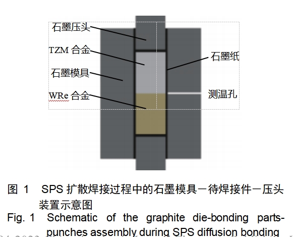
The cylindrical rods of TZM and WRe alloys were pre-grinded with 400~2000 grit silicon carbide sandpaper, then polished and ultrasonically cleaned in alcohol, dried and prepared for use. The treated TZM alloy and WRe alloy cylindrical rods are put into the graphite mold with an inner diameter of φ11.4mm in order from top to bottom, and then pressed by the upper and lower indenter, and at the same time, the surface to be welded is located in the middle of the height of the graphite mold; between the specimen and the inner wall of the graphite mold as well as the specimen and the upper and lower indenters are separated by 0.2mm smooth and flexible carbon paper in order to prevent the specimen from bonding with indenter and inner wall of the mold for the convenience of the sintering process. and the inner wall of the mold during the sintering process to prevent the specimen from bonding with the indenter and the inner wall of the mold for easy demolding. In addition, a porous graphite felt with a thickness of about
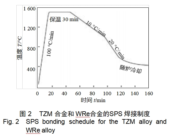
5 mm was applied on the outside of the graphite mold for thermal insulation to reduce radiative heat dissipation and temperature gradient [9]. The graphite molds containing the parts to be joined were diffusion welded in the furnace chamber of a LABOX-350 discharge plasma sintering system (SINTERLANDINC., Japan), and an axial pressure of 1.9 kN (20 MPa) was applied when the vacuum level was below 6 Pa. The pressure was kept constant throughout the welding process, including the heating, holding and cooling phases. The pulse sequence of the pulsed DC was 40:7. An optical infrared meter was used to align a through-hole on the outer wall of the mold (the hole diameter was 1.8 mm and was located in the middle position of the height of the graphite mold), and the welding temperature was determined and monitored. Figure 1 shows the graphite mold - to be welded parts - indenter device schematic diagram. The welding temperature was 1500°C, the holding time was 30 min, and the specific SPS diffusion welding system is shown in Figure 2. After welding, the furnace temperature is lower than 100 ℃ to remove the specimen, air-cooled to room temperature, and then demolded and remove the carbon paper on the surface of the specimen.

1.2 Performance testing
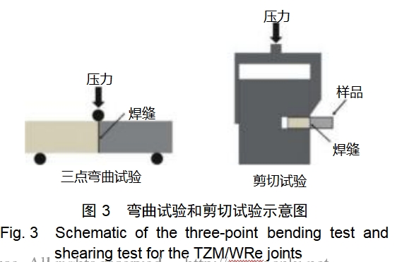
The room temperature flexural strength and shear strength of the weld were examined by using the Shimadzu Mechanical Properties Tester Model AG-100kNXplus and a homemade shear die, with the shear rate and the bending rate of 0.5 mm/min, and the bending test span of 10 mm, and the two sets of tests were averaged over three measurements. Bending specimen and shear specimen size of 16.0mm × 4.0mm × 2.0mm and 6.0mm × 4.0mm × 3.0mm, respectively, three-point bending test and shear test schematic shown in Figure 3. A quartz tube was used to vacuum encapsulate the weldment, and then placed in a muffle furnace at 1000°C and held for 15 min, after which the quartz tube was removed from the muffle furnace and cracked, so that the weldment was rapidly air-cooled to room temperature, and so on for 100 cycles to perform the thermal shock performance test of the weldment. XHVT-50Z Vickers hardness tester was used to test the hardness of TZM alloy and WRe alloy before and after welding as well as after the thermal shock test, the load was 9.8N (WRe alloy) and 29.4N (TZM alloy), the retention time was 15s, and the average value of each specimen was taken at 10 points. The weldments before and after the thermal shock test were cut along the diameter direction by wire cutting, and the specimen surface was chemically corroded after polishing. The corrosive agent was ammonia (25%) and hydrogen peroxide solution (30%) prepared in the ratio of 1:1. A German ZeissSigma scanning electron microscope was used to observe the organizational changes of the weld before and after the thermal shock test, as well as the organizational changes of the TZM and WRe alloys before and after welding. The distribution of W, Re and Mo in the weld was determined by EDS (Oxford, UK) to determine the depth of the diffusion layer of each element; 10 different areas along the weld were measured under the same magnification, and the final results were averaged.
2 Test results and analysis
2.1 Microstructure of TZM/WRe joints
High quality welded joints were obtained after diffusion welding of WRe alloy with TZM alloy by holding at 1500°C for 30 min using SPS technique. Figure 4 shows the weld organization of TZM/WRe weldments after SPS diffusion welding. From Fig. 4, it can be seen that there are no welding defects such as microholes, microcracks and unwelded joints in the welds of WRe/TZM weldments.After corrosion of the TZM/WRe joints, it can be clearly seen that the Mo element diffuses across the weld into the WRe alloy. Figure 5 shows the diffusion distribution curves of Mo, W and Re elements and their diffusion depths.The diffusion depth of Mo in WRe alloy is 2.8 μm±0.3 μm, which is larger than the diffusion depth of W and Re in TZM alloy (1.4 μm±0.5 μm). From the perspective of self-diffusion activation energy, it can be analyzed that the self-diffusion activation energy is proportional to the melting point of the material, and the melting points of W and Re (3422 and 3180 ℃, respectively) are higher than that of Mo (2623 ℃), which means that the self-diffusion activation energies of W and Re are larger than that of Mo, and therefore the diffusion rates of W and Re are smaller than that of Mo, which leads to the diffusion depths of Mo in WRe alloys are larger than those of W and Re in TZM alloys (1.4 μm±0.5 μm). The diffusion depth of Mo in WRe alloy is larger than that of W and Re in TZM alloy. In addition, from the binary phase diagrams of W-Mo and Re-Mo[10] , Mo and W are in infinite solid solution with each other, while the solid solubility of Re in Mo increases with the increase of temperature, and its maximum solubility (mass fraction) is about 55% when the temperature is 2200°C. Therefore, it is hypothesized that WRe/TZM alloys have a higher diffusion rate than that of Mo in TZM alloys. Therefore, it is assumed that the weld of WRe/TZM weldments are mainly Mo, W and Re single-phase solid solution.
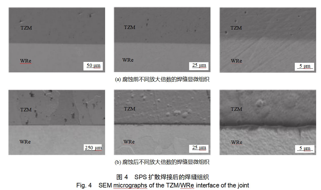
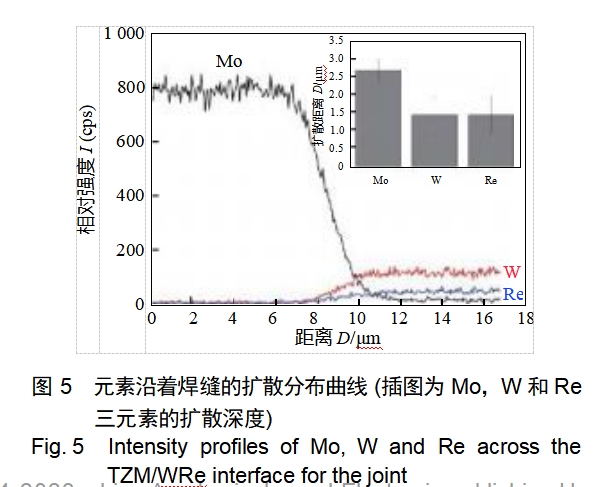
Fig. 6 shows the microstructure changes of TZM alloy and WRe alloy before and after SPS diffusion welding. The microstructures of WRe alloy and TZM alloy in the wrought state show fibrous grains (Figs. a6, 6c), and there are a large number of carbide particles diffusely distributed in the TZM alloy. After 1500 ℃ diffusion welding of the parent alloy are recrystallized, specifically for the fibrous grains after high-temperature recrystallization into equiaxial crystals, and the grain growth (Figure 6b, 6d).
2.2 Properties of TZM/WRe joints
Figure 7 shows the weld organization after 100 times of thermal shock test. From Fig. 7, it can be seen that the weld is clean and flat after the hot-shock test, and no microcracks are seen. It is analyzed that since the coefficients of thermal expansion of Mo, W and Re are very close to each other, which are 5.2×10⁻⁶, 4.5×10⁻⁶, and 6.5×10⁻⁶K-1 , respectively, the repeated and rapid temperature rise and fall during the hot-shock process will not cause excessive microcracks in the weld. Therefore, the repeated rapid temperature rise and fall during the heat-shock process will not form excessive alternating thermal stress at the weld and lead to microcracks. After corrosion, some recrystallized Mo grains in the TZM alloy grew across the interface into the WRe alloy. This suggests that the further diffusion of elements in the TZM/WRe joints during the heat-shock process contributes to the improvement of the serviceability of the weldments, and it can also be inferred that the TZM/WRe joints have excellent high-temperature properties.
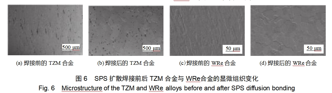

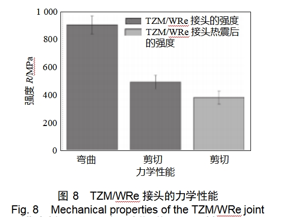
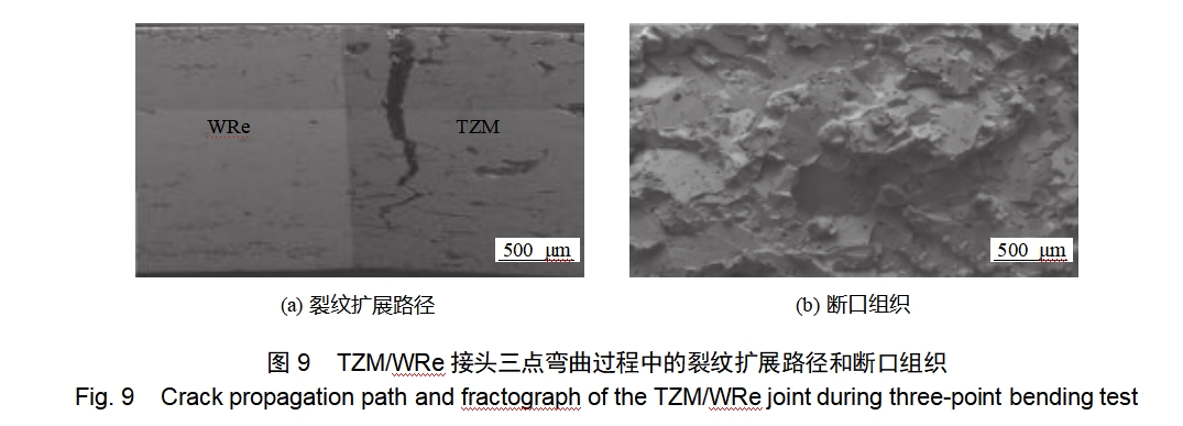
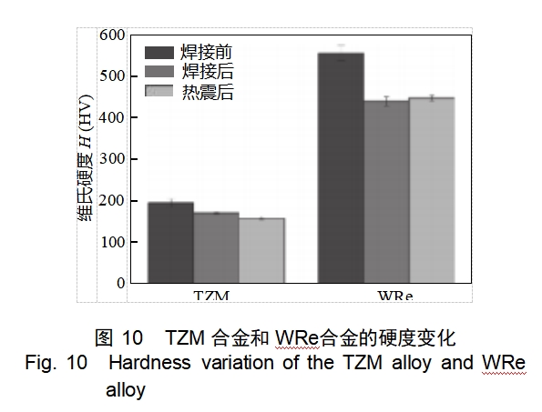
Fig. 8 shows the mechanical properties of TZM/WRe weldments under quasi-static loading conditions. The flexural and shear strengths of TZM/WRe joints are 910MPa±65MPa and 497MPa±50MPa, respectively; and the shear strength of TZM/WRe joints decreases to 385MPa±47MPa after 100 thermal shocks, which is probably due to the residual thermal stresses accumulated in the thermal shock process. This may be caused by the residual thermal stress accumulated during the thermal shock process. Fig. 9 shows the crack extension path during three-point bending of the TZM/WRe joint and the fracture organization after fracture. From Fig. 9, it can be seen that the fracture of the TZM/WRe weldment mainly occurs on the TZM alloy side, i.e., the strength of the joint is greater than that of the recrystallized TZM alloy. The fracture organization is mainly for the TZM alloy through the crystalline solution fracture. Figure 10 shows the hardness changes of TZM and WRe alloys before and after SPS diffusion welding and after thermal shock. After diffusion welding, the hardness of WRe alloy and TZM alloy is reduced compared with the hardness of the alloy in the forged state before welding due to the recrystallization of WRe alloy and TZM alloy, specifically, the hardness of WRe alloy and TZM alloy is reduced from 557HV ± 19HV and 197HV ± 10HV to 441HV ± 11HV and 173HV ± 3HV respectively, whereas the hardness values of WRe alloy and TZM alloy are almost the same after thermal shock test. TZM alloys were almost unchanged after the thermal shock test.
3 Conclusion
(1) The solid phase diffusion welding of TZM alloy and WRe alloy was successfully realized by SPS technology, with the welding temperature of 1500℃, holding time of 30min, and the weld seam was smooth without microcracks, microholes and welding defects such as unwelded joints.
(2) TZM alloy and WRe alloy in the SPS diffusion welding process have occurred in the recrystallization, Mo in the WRe alloy diffusion depth of 2.8 μm ± 0.3 μm, greater than the W and Re in the TZM alloy diffusion depth (1.4 μm ± 0.5 μm).
(3) TZM/WRe joints after 100 times of thermal shock test, the weld is intact without cracks, and part of the recrystallized Mo grain growth across the border; TZM/WRe joints of the flexural strength and shear strength were as high as
910MPa ± 65MPa, 497MPa ± 50MPa, respectively, the fracture failure occurs in the side of the TZM alloy, fracture characteristics are mainly penetrating crystals to disintegrate the fracture.
Reference: CCTS: TG456 Literature identification number: Adoi: 10.12073/j.hjxb.2018390276
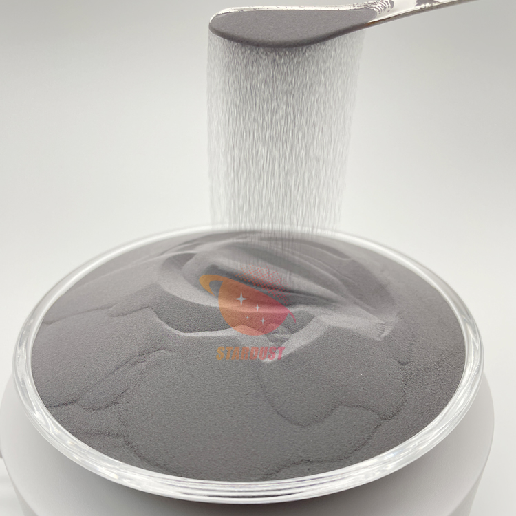
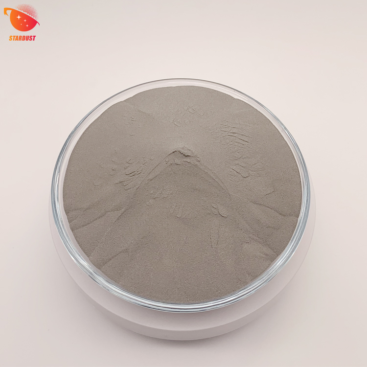
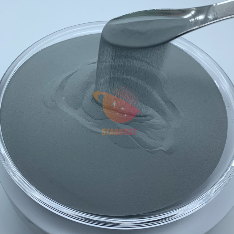
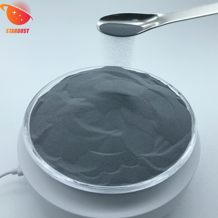
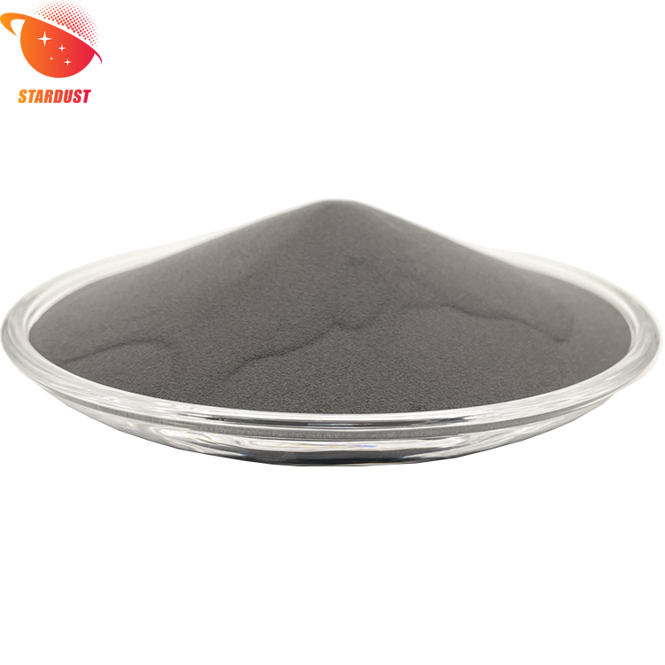
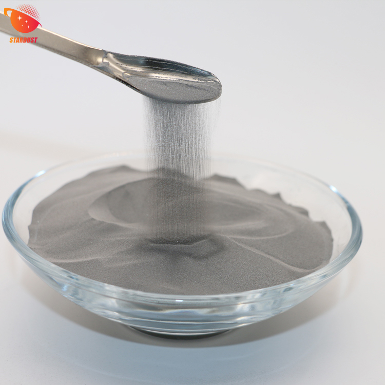
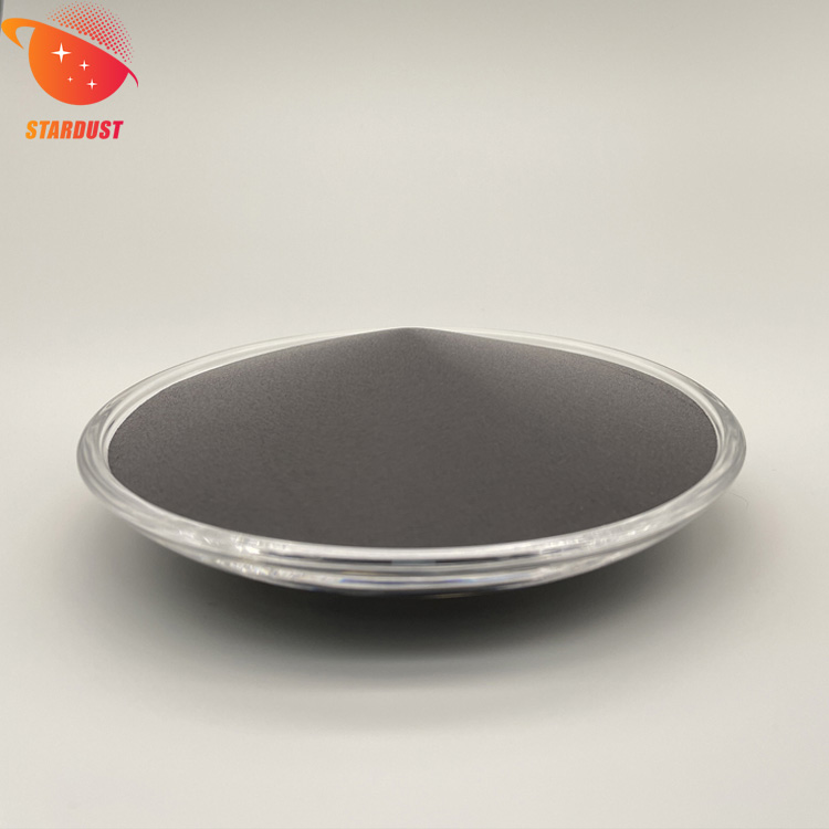
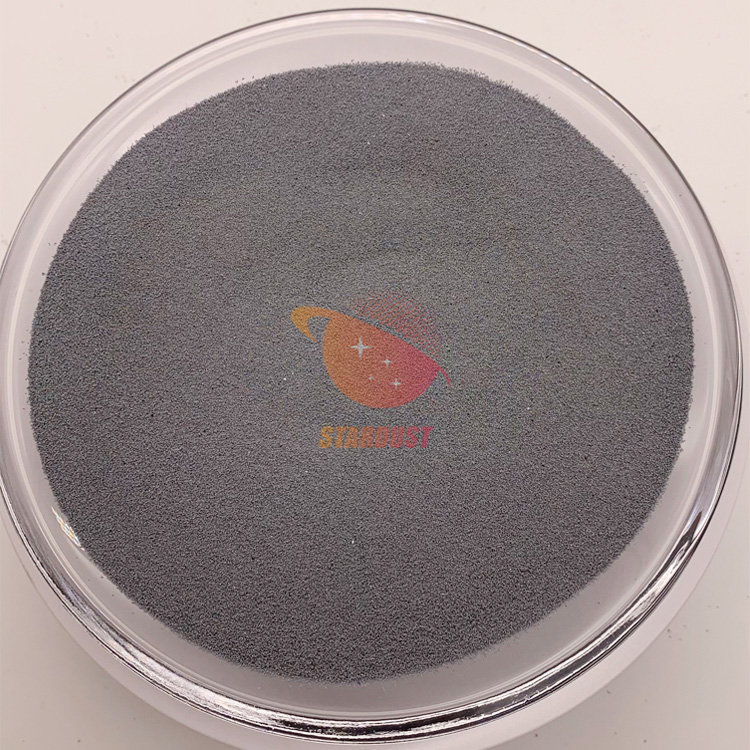
The spherical titanium-zirconium-molybdenum alloy powders and spherical tungsten-rhenium alloy powders prepared by Stardust Technology (Guangdong) Co. Ltd. using RF plasma spheroidization technology have characteristics such as high purity (low impurity content), high sphericity, no satellite spheres, excellent liquidity, and very few hollow The characteristics of our products include high purity (low impurity content)
Titanium-zirconium-molybdenum alloy powder: high density, uniform particle size distribution, combining the biocompatibility of titanium-zirconium and the high temperature stability of molybdenum, suitable for biomedical implants (e.g., orthopedic prosthesis) and corrosion-resistant parts in the nuclear industry;
Spherical tungsten rhenium alloy powder: relying on refractory high-entropy alloy system (such as W-Mo-Ta-Nb-V), with high strength, high hardness and excellent high-temperature abrasion resistance, mainly used in aerospace engine components, nuclear industry irradiation-resistant components and military field of high-load parts.
Both types of alloy powders are compatible with advanced processes such as 3D printing and hot isostatic pressing to meet the demanding needs of high-end manufacturing for material properties.
About metal powder, want to know more, welcome to contact our professional and technical staff, Manager Zheng +86 13318326187.


Signup our newsletter to get update information, promotion and insight.


 IPv6 network supported